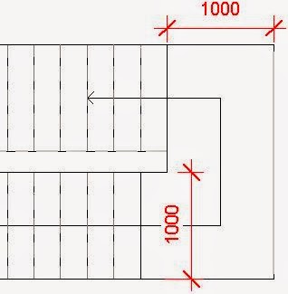
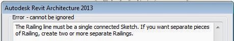
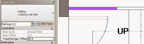
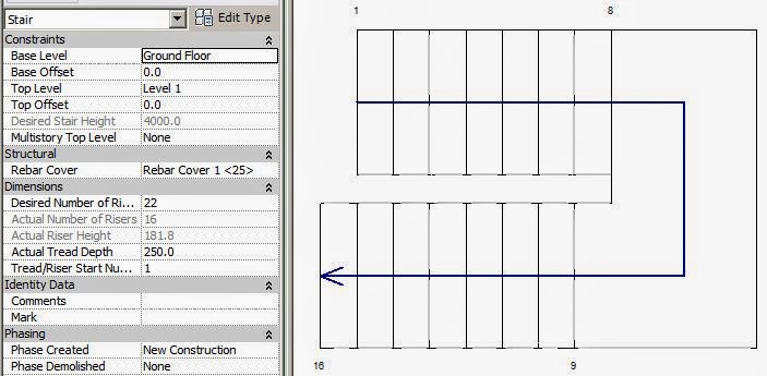
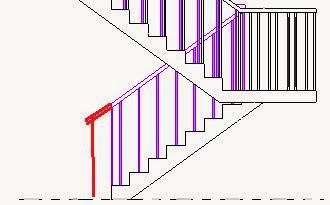
In a recent post by Andy Milburn over on Shades of Grey, he mentioned that it is not possible to indent the edges of a divided surface. Well, that is absolutely true - Divided surfaces are unlike divided paths, which have an indent setting so that you can push the start or end nodes of the path in from ends of the underlying path.
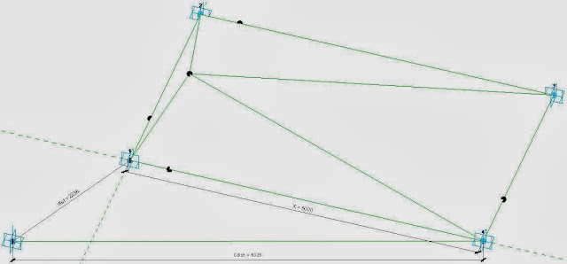
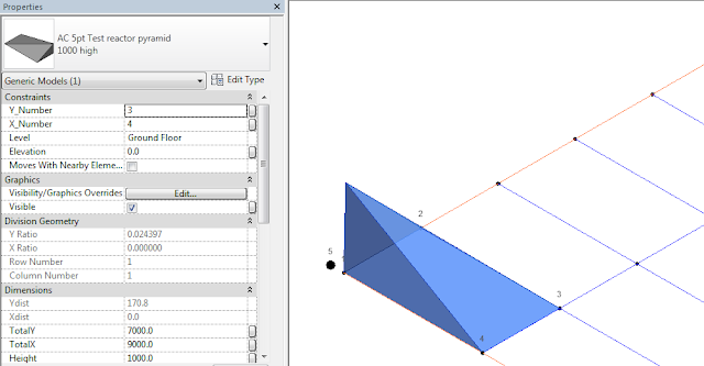
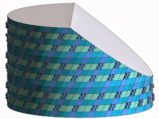
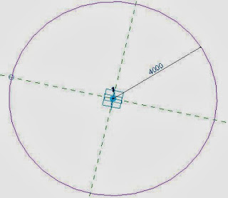
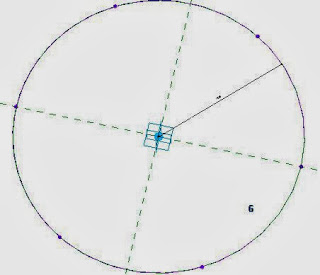
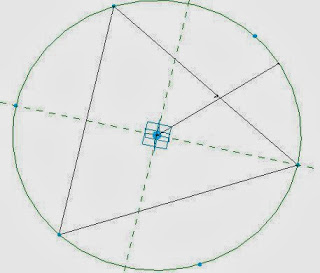
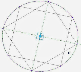
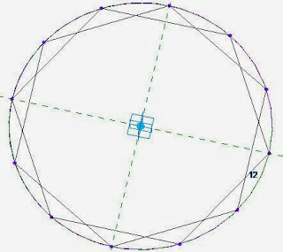
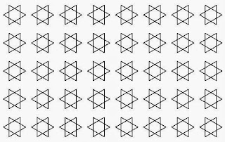
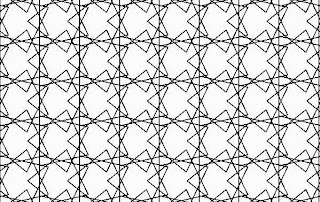
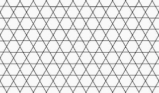
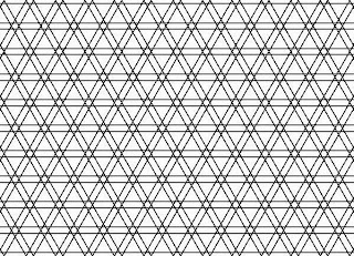
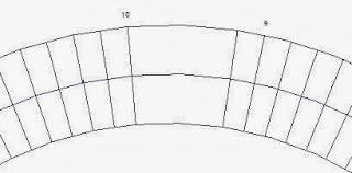
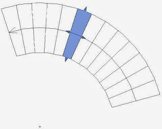
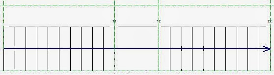
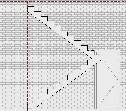
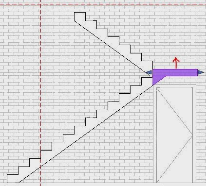
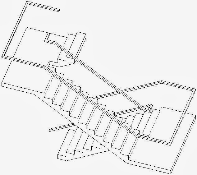
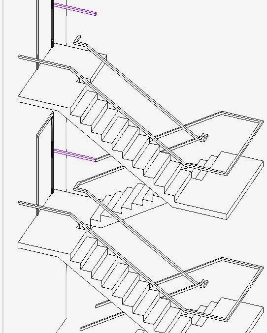
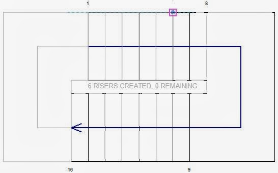
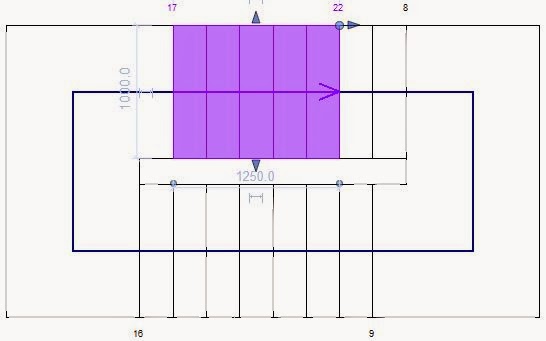
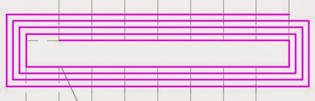
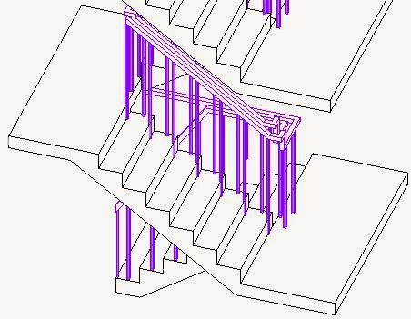
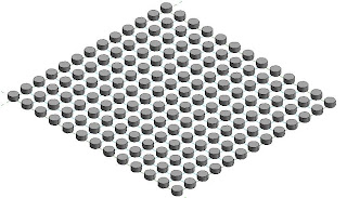
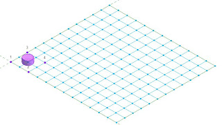
The implication of this is that when you use a divided surface to generate a "Repeater" in Revit, the repeated adaptive components will overhang the edge of the divided surface. In the example below, a one point adaptive component is placed on a node of the divided surface, then repeated - since the adaptive component consists of a cylindrical extrusion centred on the point, it is repeated to all nodes of the divided surface.
![]()
![]()
Since you cannot indent the edges of a divided surface, how can you prevent the repeater overhanging the divided surface? If you made the extrusion offset from the adaptive placement point you could make it indent on one or two sides of the divided surface, but then it would overhang even more on the other sides.
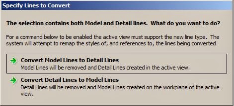
However, in Revit there is usually a way to achieve what you want, so I attempted to find a way to indent the repeater, if not the nodes of a divided surface:
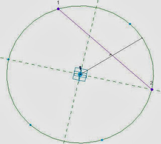
One way to do this would be to create a four point adaptive component:
![]()
![]()
![]()
![]()
![]()
![]()
![]()
![]()
![]()
![]()
![]()
![]()
![]()
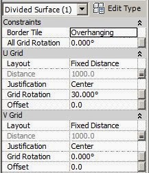
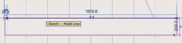
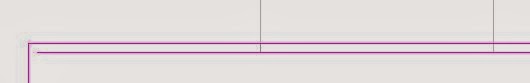
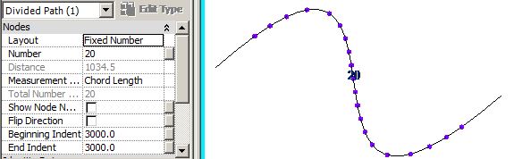 |
| Divided Path indent settings |
The implication of this is that when you use a divided surface to generate a "Repeater" in Revit, the repeated adaptive components will overhang the edge of the divided surface. In the example below, a one point adaptive component is placed on a node of the divided surface, then repeated - since the adaptive component consists of a cylindrical extrusion centred on the point, it is repeated to all nodes of the divided surface.

However, in Revit there is usually a way to achieve what you want, so I attempted to find a way to indent the repeater, if not the nodes of a divided surface:
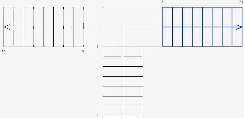
How to Indent a Repeater Pattern
You have to use some tricky thinking, and control where the repeater components will land - and prevent it from placing any part of the extrusion in the adaptive component on the edge nodes.One way to do this would be to create a four point adaptive component:
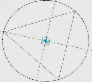
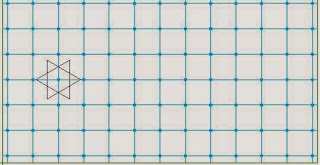
- First create a new adaptive component and place four points in a square arrangement
- Make the points adaptive
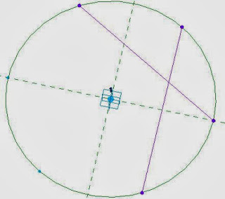
- Join the four points with four reference lines
- Place four more points on the mid-point of each reference line (watch for the triangular snap symbol
- Join those four points with two more reference lines
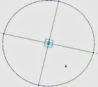
- Place yet another point on one of the central lines

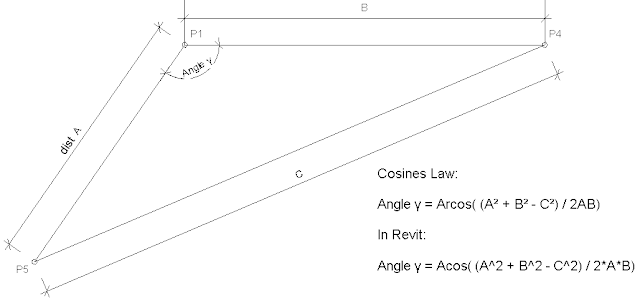
- When you select the point, it will have an option (on the Option Bar, no less) to host it by intersection

- Select that option, then pick the other central reference line
- It will move the point to the central intersection.
- NB. On reflection, you could skip the last four stages and just have one central linking reference line with a single point on its mid-point. However, you could this intersection technique for other situations - perhaps if your extruded geometry needs to be more complex than a cylinder (see later on).
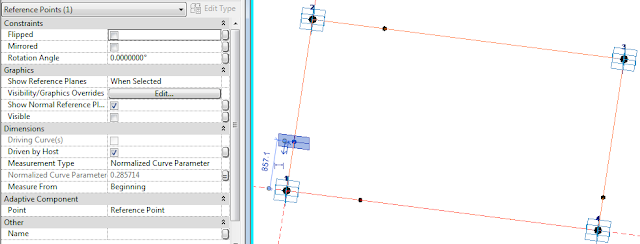
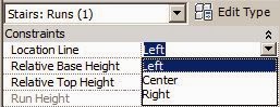
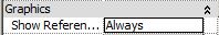
- Select the central point and set its "Show Reference Planes" to "Always"

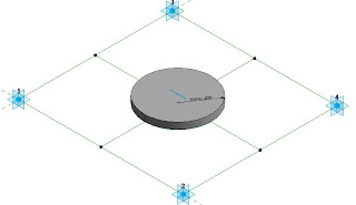
- Set the active Work Plane to the horizontal reference plane of the central point
- Place a reference circle centred on the point (assuming you want a cylinder)
- Give its radius a parameter

- Select the circle and "Create Form"
- Select the top facet of the cylinder and give its Positive Offset a parameter called "Height"
- Save and load the family into wherever your divided surface resides
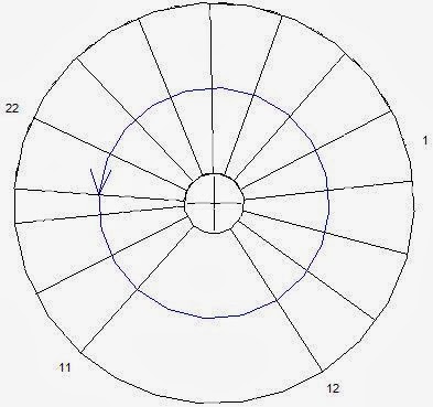
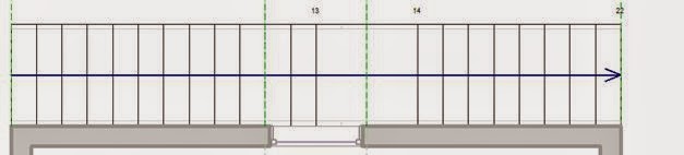
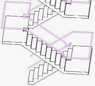
- Place one of the components onto four adjacent nodes of the divided surface in the same order that they are numbered in the family (its good practice to always use the same convention - say clockwise, unlike the diagrams shown here!!)

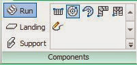
- Select the adaptive component and click on the "Repeater" command (its the Array icons, but with the letter P on it)
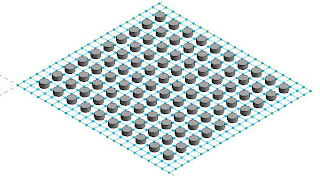
- If you snapped to the nodes correctly it should create a regular pattern
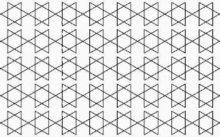
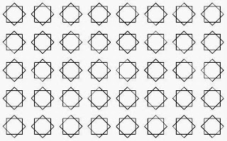
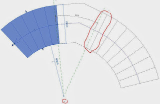
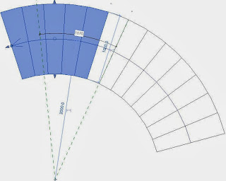
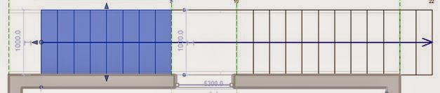
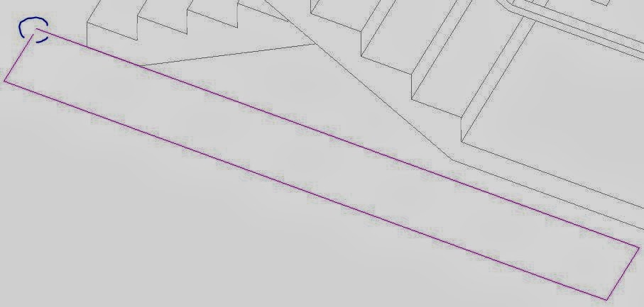
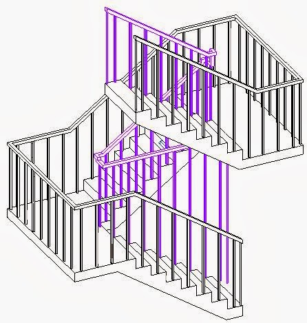
- The extruded cylinders will be inset from the edge - however, they will only be inset by half the distance between nodes

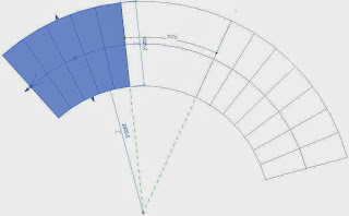
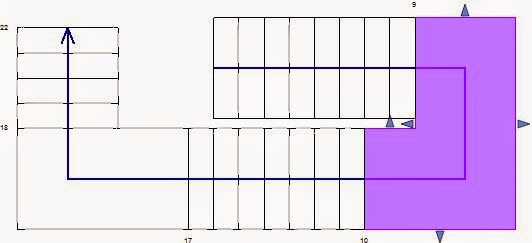
- If you want the cylinders to be inset by the full distance between nodes, you'll need to be more tricky:
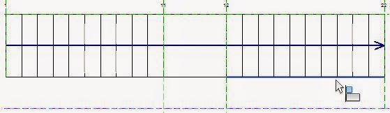
- Delete the repeater (you cannot dissolve it or alter its layout)
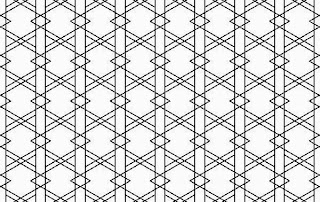
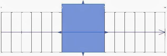
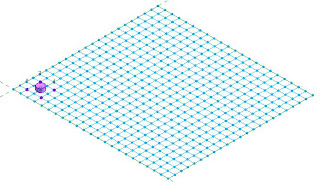
- Place a new component on alternate nodes in a square pattern
- The cylinder should then sit exactly over a node
- Select the component and "Repeat" it
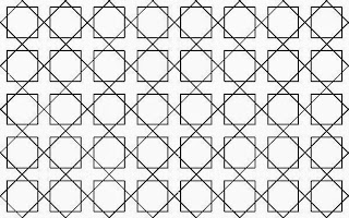
- The pattern should spread over alternate nodes on the divided surface

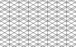
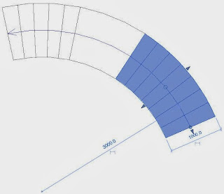
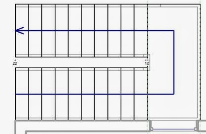
- The spacing will then most likely be too big
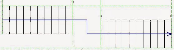
- Select the divided surface and double the number of divisions (or half the spacing if it is set by distance)
- Oops - we've now ended up with the same indent as before, so we may need to try another trick

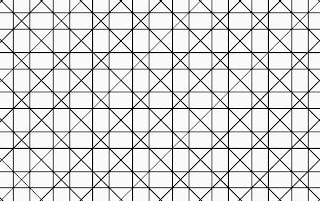
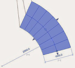
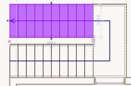
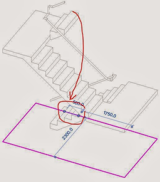
- The answer here is to coerce Revit into doing what you want by indenting the initial placement of the component
- Make sure that the first placement node you select is one node in from both edges
- Select the component and repeat it
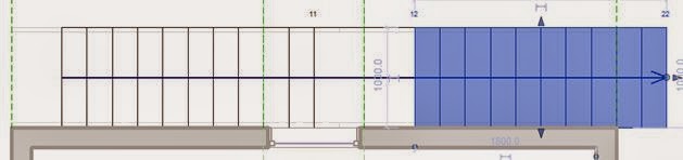
- This will only work if the number of divisions is equal; it will probably no longer work if you start playing around with number of divisions after repeating the component - so it pays to set the number of divisions correctly to start with.
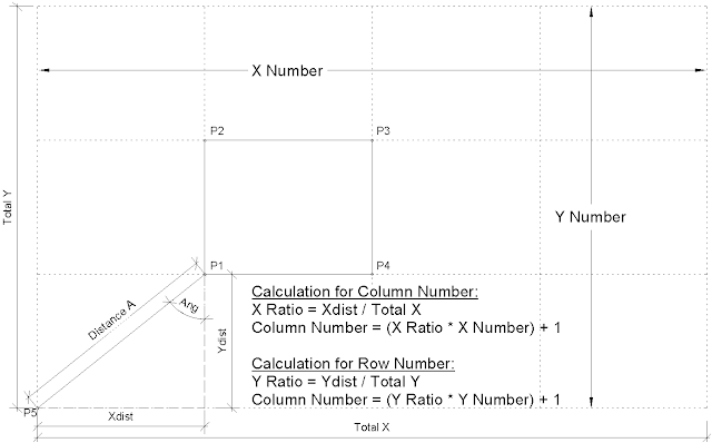
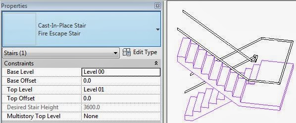
If you want to be really clever, you could go back to the original four point adaptive component and give it some reporting parameters and use them to drive the cylinder size depending on the divided node spacing